Home / Services / Reverse engineering and 3D scanning
Reverse engineering, 3D scanning and prototyping
When a part is obsolete, undocumented or worn out, the physical part becomes the drawing. Scanned or measured directly, modelled parametrically, dimensioned to a manufacturable drawing and verified against the original before anything is cut.
Parts go out of production, drawings go missing, and tooling wears out long before the part it makes is retired. The machine still has to run on Monday. Reverse engineering turns the part in your hand into something you can have made again — this year and in ten years.
Scanning and measurement
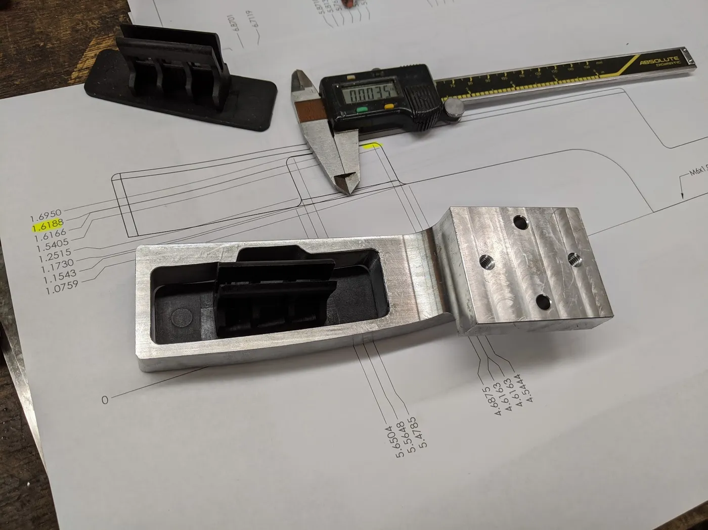
3D scanning for organic and complex surfaces, direct metrology for prismatic features where a caliper, height gage or CMM gives a truer number than a point cloud. Most parts need both: the scan carries the shape, the measurements carry the dimensions that matter. Which features are critical is agreed with you, because that decision drives cost.
Mesh to parametric CAD
A scan alone is a mesh — useful for reference, not for manufacturing. The model is rebuilt parametrically in SolidWorks with real features: planes, holes, bosses, fillets and threads, driven by dimensions you can change later. A model built this way can be scaled, corrected or adapted when the next revision comes, rather than re-scanned.
Restoring intended geometry
A worn part is evidence, not a specification. Worn, dented and corroded areas are identified and restored using symmetry, mating components, standard thread and bearing sizes, and the original manufacturing method. Assumptions are written on the drawing so you can confirm them rather than discover them.
Legacy tooling, dies and fixtures
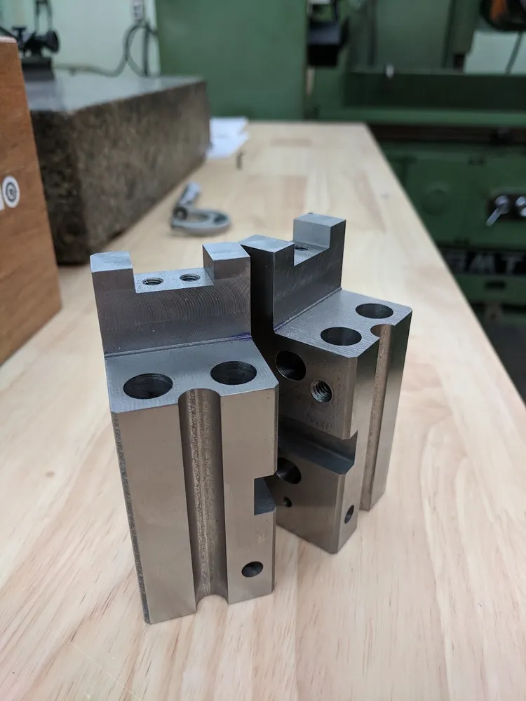
Crimp dies, swage tooling, work-holding and gauging fixtures, and discontinued machine components remade from the surviving sample. Where the original was built to an obsolete standard, the replacement is brought to current material and hardware availability without changing the function.
Injection mold cavity and core design
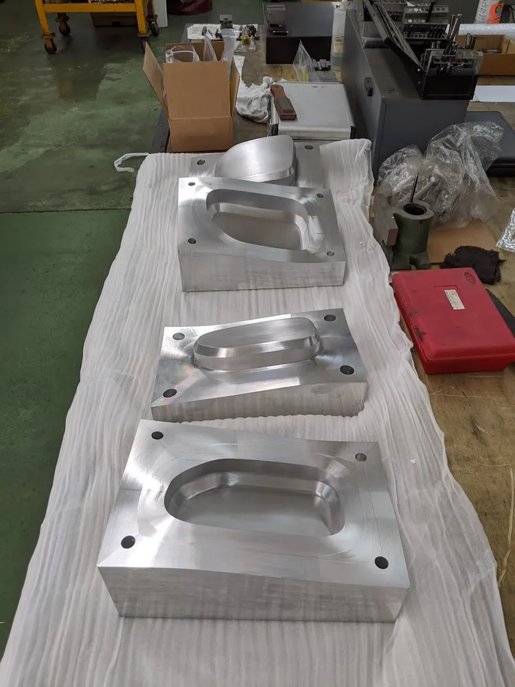
Cavity and core sets designed from the part model or from the moulded part itself: parting line, draft, shrink allowance, gating, venting and ejection, with block sizes matched to your press. Mold blocks and tooling are machined by partner shops under ENQUIPA drawings.
Prototyping
3D printing in-house, so a form-and-fit prototype can be in your hand within days of the model being finished — the cheapest way to find out that a bracket fouls a hose before you machine it in aluminium. Production parts follow through CNC machining, fabrication and industrial additive (SLS, MJF and metal) with partner shops.
What you get
- Scan data and measurement record
- Parametric CAD model (SolidWorks native, plus STEP, IGES, Parasolid)
- Dimensioned, manufacturable drawing package with material and tolerance callouts
- Verification of the model against the physical part
- Form-and-fit printed prototype where it helps
- Machined or moulded parts through partner shops, if you want the part and not just the file
Typical lead times
1 to 4 weeks for a part; longer for multi-cavity tooling. Confirmed in a fixed-price quote after a scoping call. No hourly billing.
Questions we get
- We have no drawing at all. Can you still make one?
- Yes — that is the normal starting point. Send the part or a photo with a scale in frame.
- The part is worn. Will you copy the wear?
- No. Worn surfaces are restored to intended geometry, and the assumptions are stated on the drawing.
- Do you sign an NDA first?
- Routinely. Nothing is published without written permission, which is why the case studies here are anonymised.
- Can you design the mold as well as the part?
- Yes — cavity and core sets, dies, swage tooling, work-holding and gauging fixtures.
From part to drawing to tooling
CUSTOMER NAMES WITHHELD